
DF Series
Intelligent Liquid Level Controller
Introduction
DF series intelligent high and low liquid level controllers with built-in integrated circuits are specially designed for the water pool management of family and factories. DF series smart water level controllers are widely used in various industrial fields, such as printing, dyeing, chemical, food, feed, wine, and sugar. With high-precision water level probes, DF series intelligent water level controller can realize automatic water replenishment and drainage of the water pool, as well as combined control of upper and lower pools. DF series water level controller also has functions such as water shortage protection, which can prevent the water pool from overflowing due to high water level and damage to the pump due to idling. DF series water level controllers are suitable for "Water tower-Well" water supply systems in cities, towns, rural areas, schools, factories, and mines, as well as the water level elevation of urban high-rise buildings. According to the installation method, DF series water level controllers can be divided into wall-mounted type (DF-96A, DF-96B, DF-96C) and DIN rail mounted type (DF-96D).
Parameters
DF-96A/96B/96C (Wall Mount)
Operation Voltage: DF-96A/96B/96C: AC220V; DF-96C: AC380V;50/60Hz (or other customized voltage)
Switching Capacity: 16A (DF-96A),20A (DF-96B/C); COS=0.9
Weight: 350g
Dimensions: 126×88×51mm
Mounting: Wall
Signal distance: ≤30m(the cable length can be customized according to specific requirement) image")
DF-96D (DIN Rail Mount)
Operation Voltage: AC200V±10%,50/60Hz
Switching Capacity: 5A; COS=0.9
Weight: 165g
Dimensions: 100×50×74mm
Mounting: Rail
Signal distance: ≤150m (the cable length can be customized according to specific requirement) image")
Note: The switching capacity in the above basic parameters is based on resistive load. If the load is an inductive load or a capacitive load, the corresponding switching capacity is 30-40% of the resistive load.
Dimensions & Wiring Diagram
DF-96A/96B/96C (Wall Mount)
1 Single Phase Power Supply
1.1 Direct control method (as shown in Figure 1)
Applicable object: single-phase AC water pump, and the power consumption of the controlled water pump does not exceed the rated switching capacity of the water level controller.
1.2 Single-phase expansion method (as shown in Figure 2)
Applicable object: single-phase AC water pump, and the power consumption of the controlled water pump exceeds the rated switching capacity of the water level controller. If this wiring method is adopted, the output terminal of the water level controller needs to be connected to a single phase AC contactor whose switching capacity should larger than the power consumption of the load to expanse the switching capacity of the water level controller. For DF-96A and DF-96B, you should choose an AC contactor whose coil voltage is 220VAC; for DF-96C, you should choose an AC contactor whose coil voltage is 380VAC.
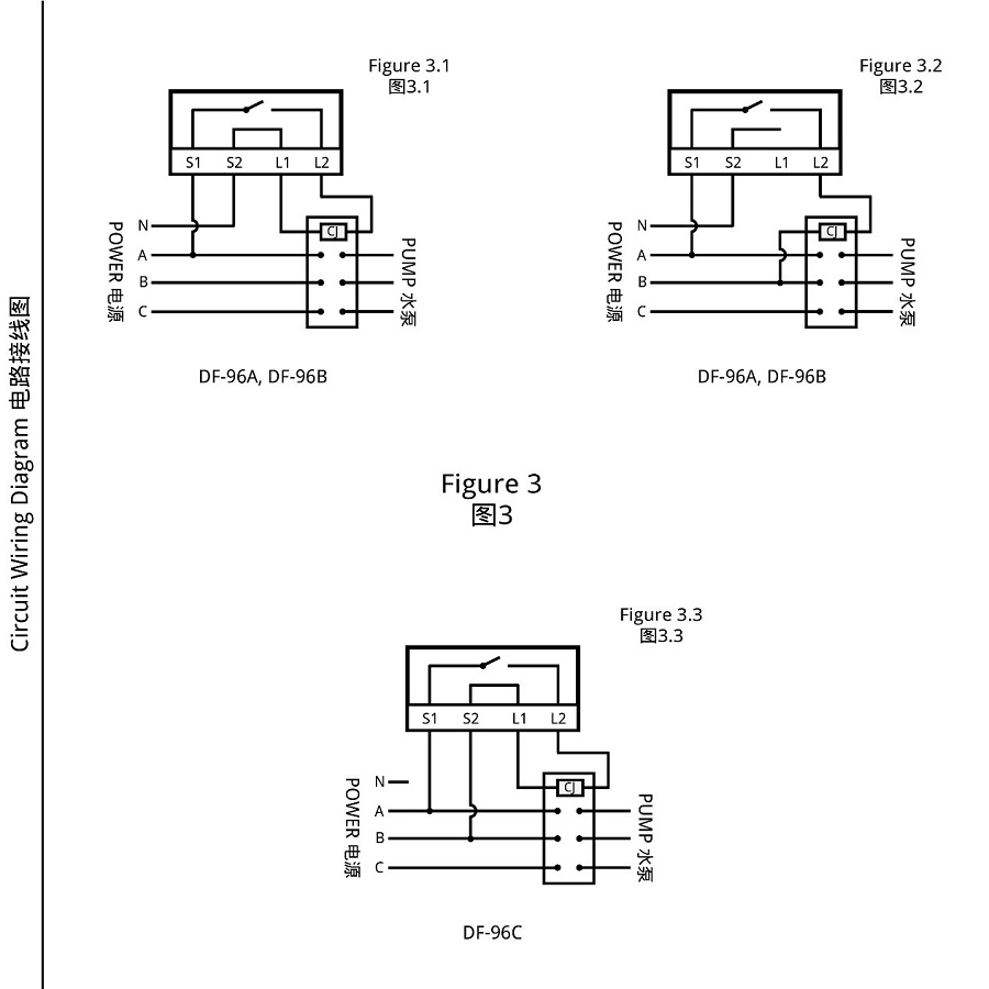
2 Three Phase Power Supply
Applicable object: Three-phase AC water pump. If this wiring method is adopted, the output terminal of the water level controller should be connected to a three-phase AC contactor.
2.1 If the coil voltage of the AC contactor is 220VAC/50Hz, please wire the DF-96A or DF-96B as Figure 3.1 shows.
2.2 If the coil voltage of the AC contactor is 380VAC/50Hz, please wire the DF-96A or DF-96B as Figure 3.2 shows.
2.1 If the coil voltage of the AC contactor is 380VAC/50Hz, please wire the DF-96C as Figure 3.3 shows.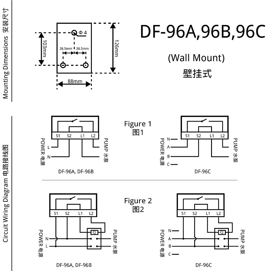
DF-96A/96B/96C wiring diagram 1
DF-96A/96B/96C wiring diagram 2
DF-96D (DIN Rail Mount)
As shown in Figure 4, the output contacts of DF-96D are a normally open contact (PORT4) and a normally closed contact (PORT5). According to actual needs, you can choose different wiring method (Normally Open, Normally Close, Single Pole Double Throw).
1 Single Phase Power Supply
1.1 Direct control method (as shown in Figure 5)
Applicable object: single-phase AC water pump, and the power consumption of the controlled water pump does not exceed the rated switching capacity of the water level controller.
1.2 Single-phase expansion method (as shown in Figure 6)
Applicable object: single-phase AC water pump, and the power consumption of the controlled water pump exceeds the rated switching capacity of the water level controller (resistive load 10A, inductive load 5A). If this wiring method is adopted, the output terminal of the water level controller needs to be connected to a single phase AC contactor whose switching capacity should larger than the power consumption of the load to expanse the switching capacity of the water level controller.
2 Three Phase Power Supply
Applicable object: Three-phase AC water pump. If this wiring method is adopted, the output terminal of the water level controller should be connected to a three-phase AC contactor whose coil voltage is 220VAC/50Hz (as shown in Figure 7).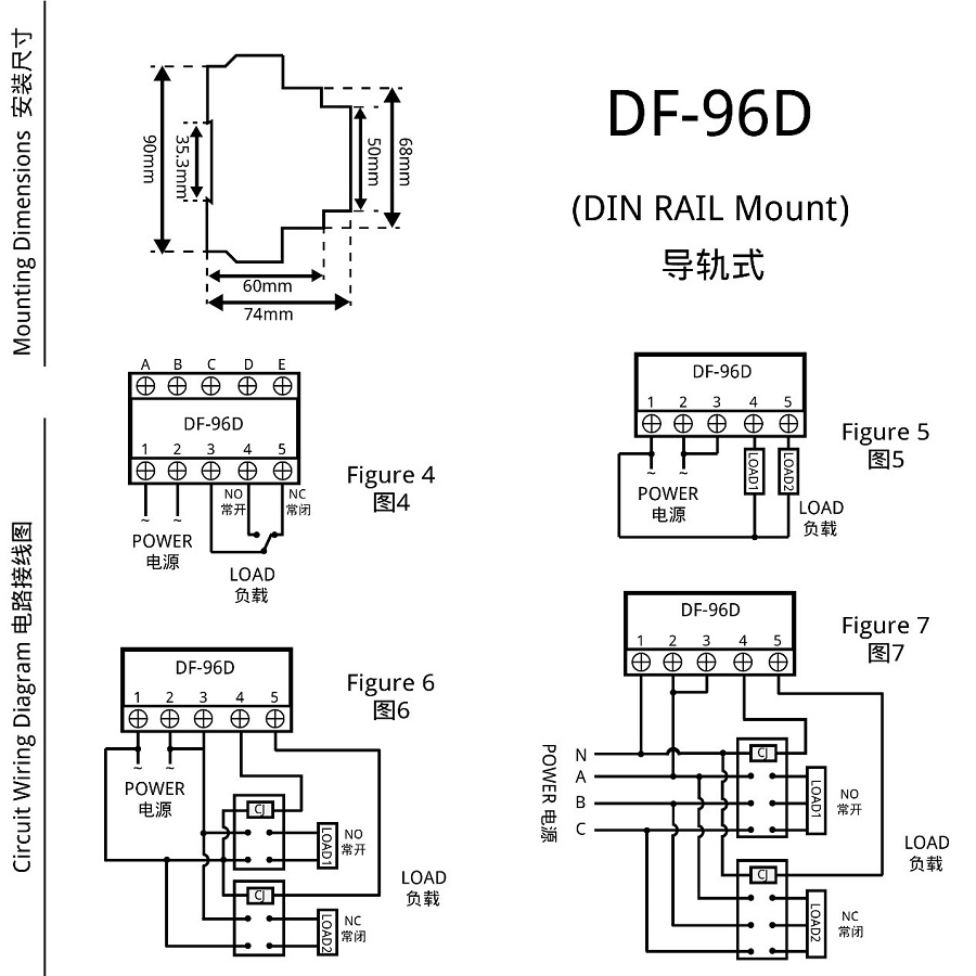
DF-96D wiring diagram
Instructions For Use (How to set)
- 1 What is the function of each probe (water level control wire)
A (Red Wire): It is the upper limit water level control point of the upper pool (reservoir). When the water level rises to A point, the water surface contacts the probe A, and the water level controller automatically turns off the water pump and stops water injection.
B (Blue Wire): It is the lower limit water level control point of the upper pool (reservoir). When the water level drops below B point, the water surface is out of contact with the probe B, and the water level controller automatically turns on the water pump to start water injection.
C (Black Wire): It is the ground wire of the pool (reservoir). It needs to be placed at the lowest point of the pool in contact with the bottom of the pool.
D (Green Wire): It is the lower limit water level control point of the lower pool (drainage pool). The water level drops below D point, the water surface is out of contact with the probe D, and the water level controller automatically shuts off the water pump and stops draining.
E (Yellow Wire): It is the upper limit water level control point of the lower pool (drainage pool). The water level rises to E point, and the water surface touches the probe E, and the water level controller automatically starts the water pump and starts draining.2 How to wire the probe2.1 If you control the water level of the upper pool separately, you can connect as shown in Figure 8.1, that is, A is connected to the upper limit of the water level, B is connected to the lower limit of the water level, C is connected to the bottom of the pool, and D and E are connected to C.
2.2 If you control the water level of the lower pool separately, you can connect as shown in Figure 8.2, that is, A and B are not connected, C is connected to the bottom of the pool, D is connected to the lower limit of the water level, and E is connected to the upper limit of the water level.
2.3 If you control the water level of the lower pool separately and also need the water shortage protection function, it can be connected as shown in Figure 8.3, that is, A and B are not connected, C and D are connected to the lower limit of the water level, and E is connected to C.
2.4 If you need to control the upper and lower pools together, you can connect as shown in Figure 8.4, that is, A is connected to the upper limit of the water level of the upper pool, B is connected to the lower limit of the water level of the upper pool, C is connected to the bottom of the upper and lower pools, and D is connected to the lower limit of the water level of the lower pool, and E is connected to the upper limit of the water level of the lower pool (if the lower pool does not need to be drained, it is no need to connect E).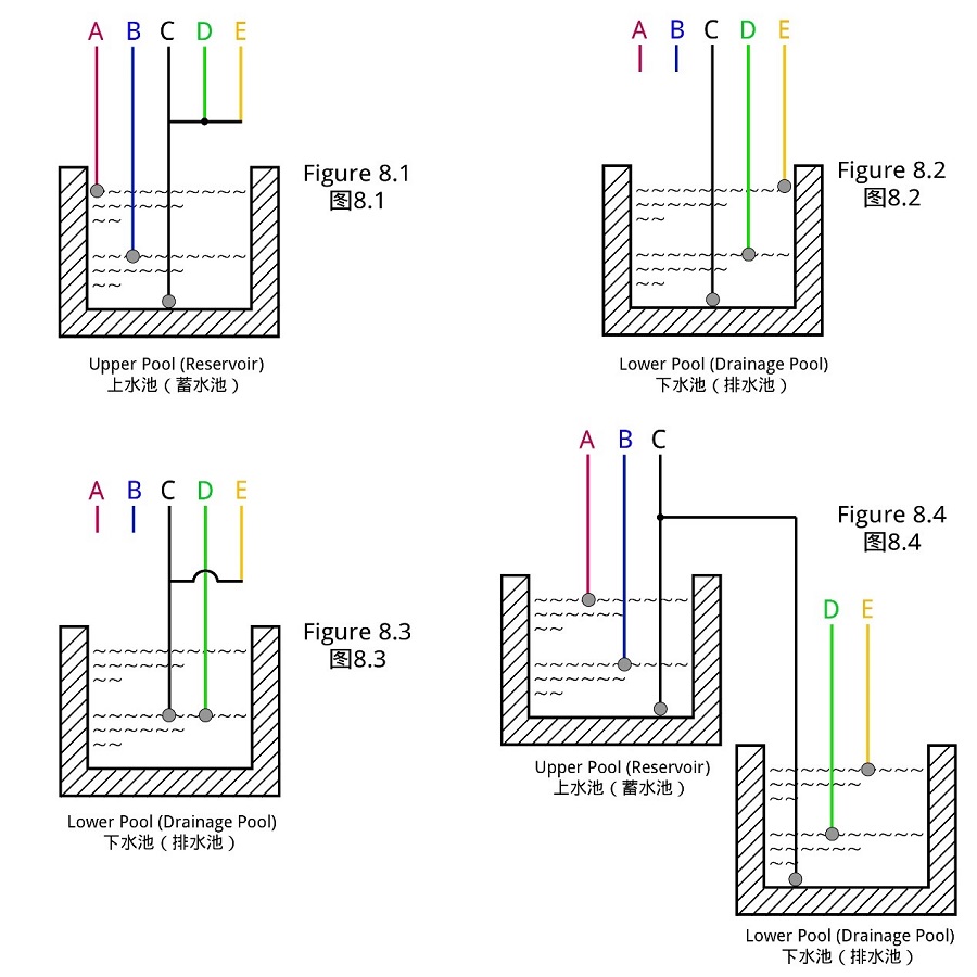
DF series probe installation
When you think there is a fault (FAQs)
1. If it doesn't work after power on
1.1 Check if the red power indicator light is on. If it does not light up, please check whether the wiring of the input and output terminals are in good contact.
1.2 Check whether the "manual/auto" switch on the right side of the product is in the "off" position. If so, please adjust it back to the "auto" position, and the water level controller will automatically enter the working state.
2. If the water level line exceeds or falls below the water level control point, the water pump does not automatically close or open, please turn on/off the water pump manually through the "manual/auto" switch and check
2.1 Whether the position of the probe is deviated, if the installation position is too high (too low), the water surface cannot touch (detach) the probe normally.
2.2 Whether the cable of the probe is correctly connected to the corresponding terminal of the water level controller, and whether there is poor contact or short circuit.
2.3 Whether the probe is corroded or falling off.
2.4 Whether the probe C (ground) has been placed in the lowest position of the pool.Attentions
1 In order to ensure the normal operation of the water level controller, after installing the water level controller, please check the wiring of the input end and the output end, and whether the connecting wire of the probe is in reliable contact. The actual working environment can be simulated by moving the probe up and down (to contact or leave the water surface) to detect whether the water level controller is installed correctly and functions normally.
2 It is recommended to fix each probe on the inner wall of the pool to prevent the water level controller from malfunctioning due to the shifting of the probe position. If the material of the inner wall of the pool is metal, all probes except probe C (ground) should not be connected to the inner wall to avoid short circuit and cause the water level controller to not work normally.
3 After connecting the cable according to the operating instructions, please check whether the water pump can be turned on or off manually through the "manual/auto" switch on the right side of the controller (DF-96D does not have this switch). After checking, please adjust it back to the "auto" position, and the water level controller will enter the automatic working mode.
4 If you need to turn on/off the water pump temporarily, please control it through the "manual/auto" switch on the right side of the water level controller (DF-96D does not have this switch).
5 In order to avoid malfunction, please do not install the water level controller in humid, corrosive and high metal content gas environment.
6 It is recommended to use the probe produced by our company.
Get in touch with us now!
Please take a minute or two to complete this simple form to get reply in 24 hours, thank you!
*Please check the trash box of your mailbox, if you do not receive our email.


